Thursday, 16 September 2010

Rudder construction

I had the rudder core CNC shaped, as it was a rather tricky shape to do by hand because of the eliptical tip and reducing thickness down the board. You also need a (curved) rebate for the carbon unidirectional which runs up either side.

The basic core with a rebate for the Carbon unidirectional either side.


The centre HD insert is cut out and then laminated and replaced. This was quite awkward to do, mainly because as soon as you cut out the HD insert, the core is reduced to a twisting floppy piece of foam, and you could quite easily loose the shape.

It would have paid me not to cut all the way up to the top but to leave a brace across to maintain the shape.(alternatively leave the core oversized at the top and trim to final size AFTER glueing back in the HD piece). Getting the insert back centrally is tricky as you cannot do it on a flat table as it just falls through the other side because  the rebate edges are higher than the center section of the core.

First layer of cargbon on.


Bagging the first layer of carbon.


Ready for the Carbon UD


One more layer of Carbon all over, then lamination just about finished.

It now joins the daggerboard for the tedious business of final fairing and shaping. I thought I would try and make some guide rails for the final shape, rather than slapping fairing mix on freehand.

 Bobstay/Screacher bracket thing.

I opted to buy the Carbon  bowpole, (which is sliding fit into the forestay/bowpole sleeve which I made some time ago)  but it does need a fitting added. Top part is where the screacher furler will attach, and the lower hole is for the wire from the bobstay fitting attached to the hull on the bow.

The bracket, (made from carbon), and a slot cut in the pole for it to fit into. Bushes will be fitted in the G10 tube later.


Trial fit. Goes in at an angle a butts up against the aft sides of the slots.


Laminated in place, and bushes fitted. I could only just reach inside the pole (with a bare arm) , to get the cloth in place, -ended up with resin stuck under me armpits! Yuck!. Also end cap fitted.

Monday, 9 August 2010

Composite Quadrant

I thought it would be worthwhile to make a composite quadrant for the steering. (10 inch radius). The one specified in the plans is available, but costs about 150GBP, - has to be adapted and is a lump of bronze weighing about 5Kg! It is a standard quadrant for a pull/pull chain and wire steering system


The basic quadrant shape.


 The intention was to have a thick flange around the curve and then carve the slots for the wire into this. A thinner flange down the sides for extra strength. . I will make 2 pieces like this then glue them together. I thought of trying to mold the slots in while making it, but even with vacuum bagging I don't think the carbon would have gone into that sort of  shape.


 Bagging the carbon. Also making a composite quadrant shelf for the sheave idler.


Glueing up the two halves


The flange at the front turned out not to be thick enough for both the wire and a deep enough  slot to stop it slipping out.  I had to add some more layers around the curve to compensate for this. Also thickened up the corners, this will allow a larger radius for the wire to go around to the fixings. (Less stress on the wire) The wires will run against the original piece, and the extra layers will just be to allow for a 8mm or so slot. to keep them in position.


 Extra layers around the curve and corners. Needs the slots cutting in for the wire , and some fixings for the tentioners to be added on each side

 
 Cutting slots with an angle grinder. Crude but effective. The blade was not thick enough for the slots I wanted, but after cutting the initial slot it is easy to widen it a little by just slightly angling the grinder off the horizontal.


Side terminaters  for the wire bonded on.


Finished. The weight with the lightening holes is 1.1Kg, which is a good saving (4Kg) on the weight of the bronze one I could have used..  A sleeve will be bonded into the centre of the quadrant  later which attaches to the sleeve/cassette in which the pull up daggerboard rudder blade is held.

I am begining to wonder if the carbon fiber will be eroded away by the constant motion of the wires in the grooves.( It is not very abbrasion reistant unfortunately)  It may be neccessary to fill in the slots with a high density resin putty and then recut them!. I had a comment suggesting using Dyneema (synthetic rigging rope?), instead of wire, -this is a possibility I guess as long as the rope does not get to abbraded in the conduits which will lead from the steering pedestal to the quadrant. Rope would certainly be less damaging to the carbon fibre.

Tuesday, 20 July 2010

Gudgeons and start of rudder

I thought I would make some of the parts for the steering. I don't know what the final arrangement will be but I will be needing a rudder, sleeve, gudgeons and some sort of rudder web to attach the gudgeons to.


Gudgeon mold and released laminate

More layers inside. Messy and sharp!

Trimmed and cut into 2 slices (on bandsaw)
A piece of modern art - no just trying to get HD fill level. God bless hot glue!

Finished gudgeons.


Cutting foam for the rudder. Cut outs for some of the HD inserts.


The foam sheet I am using is very warped, (and perforated,) so I had to make a good resin proof flat bed to glue the foam blank up on. I want to get the core CNC shaped, and to start with a warped blank would not be good at all!


Ready for glueing. As I don't know if the CNC shaping will be done in one piece, or 2 halves I am just glueing up the two halves at present. It is also more difficult to keep 4 layers plus inserts in the right place. Easier to just do it in 2 layers to start with and then glue these two together later..
The finished rudder blank, ready for shaping. It has taken quite a lot of work altogether. I find glueing up large areas can be problematic, as  it is hard to judge the thickness of the glue you are putting on. (I am also admit to being a bit of  a messy gluer!)

I had problems because the HD inserts which I glued up seperately from the main board ended up being a fraction thinner  than the rest of the board. It means when you glue these in place you have to try to hold them centrally in the board. (The centre glue line of the board is the ideal refference point for the shaping) The board has a bit of flex to it as well. I will have to be careful when laminating that nothing is under any stress or flex.

HD and nomal foam

It would I think have been better to do it all in one piece and vacuum bag it. This would have kept everything in the right place and even. Fortunately the board is over thick by about 5mm per side, which should mean that there will be enough material for the shaping.


I have added an extra area of HD foam around the tip and leading edge, just for strength. If you hit anything under the water, this is the area that will make contact first. first.

 I seem to have found a company place which will shape the block for me on a 5-axis CNC machine. We decided to do it in one piece, rather than two. This is mainly because the trailing edge of the finished (slightly undersized) blank is only about 3/4mm wide, -on each half this would reduce to 2mm, at which point the foam is going to disintegrate or get damaged. It also means that you would not have to glue up the two halves and worry about them slipping about.

Thursday, 3 June 2010

Daggerboard

I started the daggerboard about 18 months ago, but gave up on it for a while, partly because it is rather tedious and partly because I was not sure how to maintain the correct profile up and down the board. The core is shaped from Western Red Cedar. Once you have started shaping, there is very little in the way of refference points to keep you on track.

I removed as much material as possible using a router, but this is a bit limited as you get up to the non shaped area. The only refference point I really have is a good center line up and down each side .I thought if I could get the correct profile (at the right angle) on the leading edge and trailing edge, this would at least be a start.

The shape is on a sliding piece of wood that should hold it perpendicular to the side and on the center line aadn at the correct angle..


The trailing edge is straight for about the last  12 inches which is  easy to shape.

When I started the daggerboard, I did not know that it was possible to buy a ready made blank, (Phill's Foils,or I think I would have gone for that.option. I had already bought the wood and glued up the board, so I thought I might as well try and finish it. The only plus side is that as the wood has been indoors for about 18 months, it is very well seasoned and lighter now than when I left it before.

I found an interesting article about designing and making foils here: http://www.gurit.com/core/core_picker/download.asp?documenttable=libraryfiles&id=1113 , actually from SP systems who manufacture the Ampreg resin I am using. It seems that for the stiffest board with minimum tip deflection, carbon UD either side of the board is the way to go.


Laminating the Carbon, centered on the widest part of the foil shape. I wish that I had sealed of the wood first as I had some bubble trouble under the UD. Before laminating the rest of the board I sealed the wood off with 2 coats of resin, and this put a stop to that.


 To avoid any distortion across the tressels I stood the board on its side before the Carbon UD layers were fully set, and did the same with the glass layers.

The trailing edge is very thin and prone to damage. (especially on the undersized blank.) I think it would only take a small ding on this edge,  and there would be wood and water contact.  To avoid this I replaced 2 inches of the trailing edge with a HD putty mix.


 I would have liked to have done the same on the leading edge, but I should really have done this before shaping. To compensate a bit I have arranged it so that there are 2 layers of glass over the leading edge and also over the tip.


Wrapping the board up.


Board glassed all over. The shape is not yet 100%, but I thought it was best to get the Carbon and glass on first and then do the final tweaking. I am pretty sure that it is a little undersize, and will need a bit of filling and fairing to perfect the shape. Weight wise I reckon it must be in the 18/ 20Kg area. I can just about lift it on and off the tressels on my own.


Sealed holes for the pull up/down lines

Friday, 14 May 2010

Beam/float sleeves and a few repairs

I was not very happy with the laminates around the bolt on the tip of the beam. When I did the "wraps", I slit the cloth and tucked it  around the bolt, but it did not co-operate, and left a lot of air and lumps and bumps. I decided to grind them out and fill with hd putty and patch as well. You then need to recreate a flat surface perpendicular to the bolt, for the nut to tighten up against.

I used the nut and some cut offs of MDF for that. Will be wrapped in plastic tape before use.

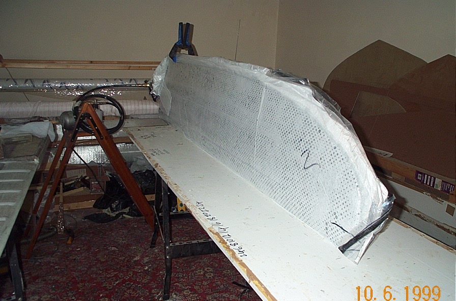
I thought I might as well make the float/ beam sleeves while I was at it. Made by wrapping fiberglass around the tip area and then pulling off.


Fairing mixture on the tips to just above the float deck level.

Fairing off the tips and re-drilling the pivot pin access holes in the beam sides. I found that shining a bright lamp down the slots in a darkened room lit up the pivot holes very well underneath the fiberglass. These holes had been sealed of with a foam plug and some hot glue. I was able to drill them very accurately using this method.

Tips faired off.. The geometry is such that the sleeve should not get locked on due to the shape. The tip is tapered up/down and sideways. In fact once you have managed to get the sleeve to move even a couple of mm, the whole thing should then slide off easily. (In theory!)


Resin proofing the tips. Parcel tape and wax. I find that although it is true to say that the resin does not stick to plastic tape, it still needs a bit of a jerk to come off. I may make a couple of handles somewhere on the sleeve to give me something to hold onto when I try to pull them off..


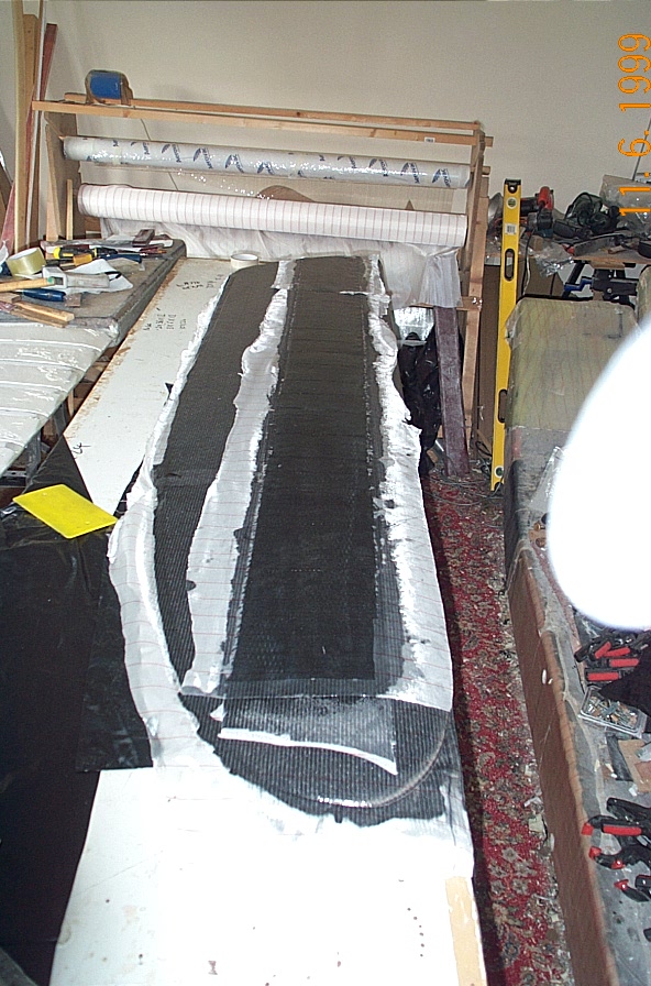
Getting the cloth ready. To be continued....


The bolt on the tip has been a constant nuisance, it is just begging to get damaged or covered in resin!


I made a raised ridge where the sleeve will be trimmed off , it should save me damaging the beam itself, and means there will be less sleeve to try and get off.


The sleeves laminated on.

I glued on the  bolt washer on the aft beams with HD putty, but this was not a good idea and just made them harder to get off.

After laminating, none of the sleeves would budge at all.! In the end I bonded on some wooden blocks and used a hammer to tap them off. But before that I did as much as I could to break the seal between the plastic tape and fiberglass. I used a 12V car tyre inflator to pump some air up the sleeve. This broke the resin/fiberglass seal in some places, but not over the tip or down the sides. It is also difficult to get a proper seal around the edge of the sleeve. I used some vacuum bagging rubber tape. Without breaking this resin fiberglass seal first, I very much doubt weather I could have got them off at all.

Wooden blocks bonded on the sides and pointing at the tip.


 Success. They are a very tight fit around the beams. When you pull them off, there is a suction/vacuum effect trying to hold them on. A small hole drilled in the tip helps to release them.

Aft beam sleeves finished. And no resin in the bolt threads.  FWD beam sleeves are still stuck fast, and the air compressor has broken down. (I may have burned it out by running it from a battery charger, I  am not sure.)

Anyway I am awaiting a replacement, as the sleeves will not budge at all without some more releasing under the fiberglass.

 Fwd beam sleeves finally finally off! Bastards! What a struggle - hours and hours of agro and frustration! Using compressed air did not work as it is virtually impossible to get a good seal around the sleeve. They would just not come off with tapping alone, (wood blocks got completely mashed with hammering) and in the end I  had no option but to try and cut them off, without damaging the beam. Not a happy situation to be in. I am doubly annoyed because my gut instinct when I laminated these on was that they would not come off. The shorter AFT sleeves yes, but not the longer FWD ones. The whole thing is a recipe for disaster. You cannot physically exert enough force to overcome the friction/tightness.

In the end I managed to push an old hacksaw blade partly up the middle of the sides, and then using a Feinmaster type cutter, I made 9 inch slits up the sleeve sides,  trying to cut on top of the hacksaw blade.  This released the tightness just enough to let me prise open the tops and bottoms with some very  thin wedges and push an old bandsaw blade up to the tip in places, thereby breaking the resin/plastic tape seal. Most of the time the blade just tears up the plastic tape and sticks, but I managed to break just enough of it so that it would tap off. The suction/vacuum effect is even stronger on these sleeves, and a hole drilled at the tip definately helps to prevent this.

I have to say nonsense like this really leaves a bitter taste and tarnishes your view of the whole project. You wonder how much punishment you want to take. I now have the pleasure of repairing the sleeves and some of the side layers on the beam itself. As a final insult, the plastic tape came off in 5000 pieces and left most of the stickness behind! Urgh!
On a lighter note thank heavens for Devcon 5-minute epoxy and the Bosch multi-tool!. The epoxy is expensive but very impressive. Within 10/15 minutes of bonding on the wooden blocks I was able to hit them with a small sledge hammer and they did not come off at all. I have had to cut/chisel the blocks off.

The multi-tool is definately my  2nd most usefull piece of kit (after the Black and Decker Power file). You can plunge cut into materials, and it cuts even fresh or thick laminate very well without damage. It is also cheaper then the Feinmaster.