Saturday 20 November 2010

Beam Baking

I am using a similar arrangement as before, but with an additional 60W bulb. 6 in total. Could really have done with 7 to speed up the process and produce some extra heat.


Bearing in mind that there is 60/70Kg of resin and glass in the beams, it is going to be a slow process to heat them up to 50C. There are 25 plus layers of carbon and glass in places, and the heat is going to take a long time to reach everywhere.


I wanted the hot air to be able to circulate all around the beam, hence the side struts to lift up the cardboard.


Cardboard creation. Unfortunately the heat loss from this was too much, and I had to add a lot of blankets and some old rugs to keep the heat in. Coud have done with another bulb, but would exceed my dimmer switch wattage rating..


Initially the heat distribution was rather poor. The hot air was trapped underneath the beam by the sides of the ladder,  and was not getting up to the top surface well (15C difference between top and bottom). I had to add 2 small hot air/cool blower fans (8.99 GBP - Amazon!)  in at each end to circulate the air better.

Finally getting up to temp after about 36 hours! The light bulb method is v slow for a big heavy part like this, but on the other hand you do not have to worry about it all going ballistic and frying the thing while you are away.  I think the maximum heat you can get from this arrangement with no heat losses would probably be about 60C, which would not do any damage.

Sunday 14 November 2010

Postcuring daggerboard and rudder

I thought it would be a good to idea to postcure the daggerboard and rudder parts for extra strength, as they are not going to be exposed to much  heat  when in position. It is not strictly neccessary, as I have not been using slow hardener on these parts. The beams on the otherhand I will have to postcure as I used slow hardener on the multiple layers of carbon UD.
  
 I am reasonably happy with the foil shape. although it has taken more filler/fairing mix than I had hoped for. I used a template CNC cut from the daggerboard DXF file  for the final shaping. Strictly speaking I think I should have postcured before filling and fairing. Hope all the filler does not shrink and crack off!


The heat source. 5 x 60W light bulbs plus dimmer switch. I  have found this to be very controllable.


Heat source under the board. The bottom edge of the board did get a bit hotter than the top, but on the whole the heat rising up from below was quite well distributed., about 5C difference between top and bottom. 


Rather crude cardboard oven. But it did the trick OK ( with a bit of additional room heating to cover the heat loss from the cardboard) . It is suprising how long a large piece like this takes to heat up. (and cool down!) You begin to think that you are not giving it enough heat, but in reality most of it it is being absorbed by the board for the first  few hours or so. After that you can begin to actual get the temp up a bit. As the board has a wooden core, I did not want to get it too hot. In the end it had about 24hours at about 45C. (Cure for the resin I am using is 50C for 16 hours.) Hopefully this will be about equivalent.


Oven No:2 for the rudder/sleeve/gudgeons/composite chainplates/bowpole/forestay backet fitting. A smaller volume to heat up, should be a bit quicker hopefully.

Friday 22 October 2010

Rudder Case

The rudder case design is such that the rudder blade itself can be raised up and down as neccessary for getting in and out of shallow water. This gives better steering control than the kick back style of rudder where very little of the blade is in actual contact with the water.

Sleeves is made by laminating around the rudder blade itself. Flanges made from some foam cut offs, and will be pulled off after laminating


I think the idea that the sleeve will slide off sideways is a little optomistic. Fortunately because the trailing edge end is open, you can prise the sleeve sides apart slightly. Then I pulled some thin strong string down to the leading edge each side, (breaking the resin/tape seal) -then with a tap from a rubber hammer, it just jolts forward slightly and then could be worked off.

Case off, make sure you get it the right way up for trimming! The top and bottom angles are not the same.


Attaching the tube to the sleeve and getting it parallel and perpendicular is tricky to get right, -get it wrong and have wonky rudder! I thought this set up plus gravity should help, as there is very little in the way of referrence points to tell if it is correct or not.
 
.
Final laminations added - now need to cut slots for the gudgeons


Slots for gudgeons. Angle grinder and power file. Very messy- black dust everywhere. (Case shown upside down)


Marine carpet for the case lining? Well I hope so. I asked Ian Farrier what  "marine carpet" was, and he directed me here, (but also said that it is no longer available!) :

http://www.office-furniture.com.au/Fabric-Options/Fabric-Options/Front-Runner-Fabric-Range.html

However it still seems to be available in the UK -as shown above . It appears to be the same material (named - Front Runner Fabric) - it matches the description well .But it does seem thinner than I was expecting. In the uncompressed state it is about 3mm thick, but when squashed goes down to about 1.5mm. I may need to use a double layer I think. (Actually IF say do not use 2 layers, rudder would move in sleeve and steering would be spongy/rubbery)
  
 Attaching the steering arm to the case.


Mold for making a removable sleeve. The flange plate is my idea to help pull of  the sleeve after laminating.


Sleeve laminated on. These small pieces of cloth are a pain to cut and work with. They keep on lifting off around corners and are prone to distorting badly.


Trial fitting the quadrant, -getting it  perpendicular to the pivot pin is important. I am still not entirely happy with the carbon quadrant, and have decided to line the slots with 3mm Aluminium to try and prevent the steering wire from eroding the carbon over time.

Thursday 16 September 2010

Rudder construction

I had the rudder core CNC shaped, as it was a rather tricky shape to do by hand because of the eliptical tip and reducing thickness down the board. You also need a (curved) rebate for the carbon unidirectional which runs up either side.

The basic core with a rebate for the Carbon unidirectional either side.


The centre HD insert is cut out and then laminated and replaced. This was quite awkward to do, mainly because as soon as you cut out the HD insert, the core is reduced to a twisting floppy piece of foam, and you could quite easily loose the shape.

It would have paid me not to cut all the way up to the top but to leave a brace across to maintain the shape.(alternatively leave the core oversized at the top and trim to final size AFTER glueing back in the HD piece). Getting the insert back centrally is tricky as you cannot do it on a flat table as it just falls through the other side because  the rebate edges are higher than the center section of the core.

First layer of cargbon on.


Bagging the first layer of carbon.


Ready for the Carbon UD


One more layer of Carbon all over, then lamination just about finished.

It now joins the daggerboard for the tedious business of final fairing and shaping. I thought I would try and make some guide rails for the final shape, rather than slapping fairing mix on freehand.

 Bobstay/Screacher bracket thing.

I opted to buy the Carbon  bowpole, (which is sliding fit into the forestay/bowpole sleeve which I made some time ago)  but it does need a fitting added. Top part is where the screacher furler will attach, and the lower hole is for the wire from the bobstay fitting attached to the hull on the bow.

The bracket, (made from carbon), and a slot cut in the pole for it to fit into. Bushes will be fitted in the G10 tube later.


Trial fit. Goes in at an angle a butts up against the aft sides of the slots.


Laminated in place, and bushes fitted. I could only just reach inside the pole (with a bare arm) , to get the cloth in place, -ended up with resin stuck under me armpits! Yuck!. Also end cap fitted.

Monday 9 August 2010

Composite Quadrant

I thought it would be worthwhile to make a composite quadrant for the steering. (10 inch radius). The one specified in the plans is available, but costs about 150GBP, - has to be adapted and is a lump of bronze weighing about 5Kg! It is a standard quadrant for a pull/pull chain and wire steering system


The basic quadrant shape.


 The intention was to have a thick flange around the curve and then carve the slots for the wire into this. A thinner flange down the sides for extra strength. . I will make 2 pieces like this then glue them together. I thought of trying to mold the slots in while making it, but even with vacuum bagging I don't think the carbon would have gone into that sort of  shape.


 Bagging the carbon. Also making a composite quadrant shelf for the sheave idler.


Glueing up the two halves


The flange at the front turned out not to be thick enough for both the wire and a deep enough  slot to stop it slipping out.  I had to add some more layers around the curve to compensate for this. Also thickened up the corners, this will allow a larger radius for the wire to go around to the fixings. (Less stress on the wire) The wires will run against the original piece, and the extra layers will just be to allow for a 8mm or so slot. to keep them in position.


 Extra layers around the curve and corners. Needs the slots cutting in for the wire , and some fixings for the tentioners to be added on each side

 
 Cutting slots with an angle grinder. Crude but effective. The blade was not thick enough for the slots I wanted, but after cutting the initial slot it is easy to widen it a little by just slightly angling the grinder off the horizontal.


Side terminaters  for the wire bonded on.


Finished. The weight with the lightening holes is 1.1Kg, which is a good saving (4Kg) on the weight of the bronze one I could have used..  A sleeve will be bonded into the centre of the quadrant  later which attaches to the sleeve/cassette in which the pull up daggerboard rudder blade is held.

I am begining to wonder if the carbon fiber will be eroded away by the constant motion of the wires in the grooves.( It is not very abbrasion reistant unfortunately)  It may be neccessary to fill in the slots with a high density resin putty and then recut them!. I had a comment suggesting using Dyneema (synthetic rigging rope?), instead of wire, -this is a possibility I guess as long as the rope does not get to abbraded in the conduits which will lead from the steering pedestal to the quadrant. Rope would certainly be less damaging to the carbon fibre.

Tuesday 20 July 2010

Gudgeons and start of rudder

I thought I would make some of the parts for the steering. I don't know what the final arrangement will be but I will be needing a rudder, sleeve, gudgeons and some sort of rudder web to attach the gudgeons to.


Gudgeon mold and released laminate

More layers inside. Messy and sharp!

Trimmed and cut into 2 slices (on bandsaw)
A piece of modern art - no just trying to get HD fill level. God bless hot glue!

Finished gudgeons.


Cutting foam for the rudder. Cut outs for some of the HD inserts.


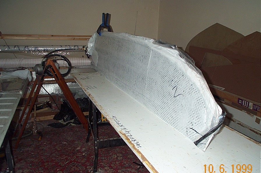
The foam sheet I am using is very warped, (and perforated,) so I had to make a good resin proof flat bed to glue the foam blank up on. I want to get the core CNC shaped, and to start with a warped blank would not be good at all!


Ready for glueing. As I don't know if the CNC shaping will be done in one piece, or 2 halves I am just glueing up the two halves at present. It is also more difficult to keep 4 layers plus inserts in the right place. Easier to just do it in 2 layers to start with and then glue these two together later..
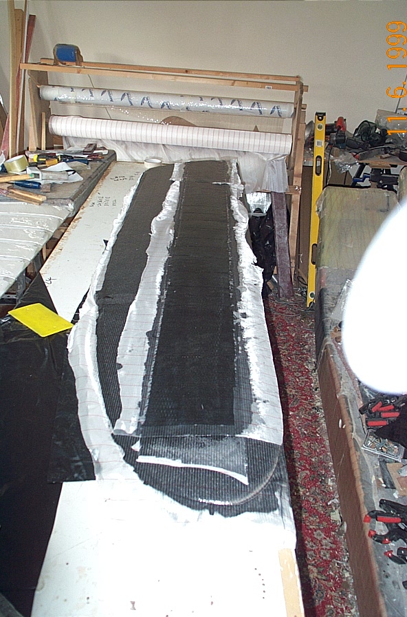
The finished rudder blank, ready for shaping. It has taken quite a lot of work altogether. I find glueing up large areas can be problematic, as  it is hard to judge the thickness of the glue you are putting on. (I am also admit to being a bit of  a messy gluer!)

I had problems because the HD inserts which I glued up seperately from the main board ended up being a fraction thinner  than the rest of the board. It means when you glue these in place you have to try to hold them centrally in the board. (The centre glue line of the board is the ideal refference point for the shaping) The board has a bit of flex to it as well. I will have to be careful when laminating that nothing is under any stress or flex.

HD and nomal foam

It would I think have been better to do it all in one piece and vacuum bag it. This would have kept everything in the right place and even. Fortunately the board is over thick by about 5mm per side, which should mean that there will be enough material for the shaping.


I have added an extra area of HD foam around the tip and leading edge, just for strength. If you hit anything under the water, this is the area that will make contact first. first.

 I seem to have found a company place which will shape the block for me on a 5-axis CNC machine. We decided to do it in one piece, rather than two. This is mainly because the trailing edge of the finished (slightly undersized) blank is only about 3/4mm wide, -on each half this would reduce to 2mm, at which point the foam is going to disintegrate or get damaged. It also means that you would not have to glue up the two halves and worry about them slipping about.