Thursday, 3 June 2010

Daggerboard

I started the daggerboard about 18 months ago, but gave up on it for a while, partly because it is rather tedious and partly because I was not sure how to maintain the correct profile up and down the board. The core is shaped from Western Red Cedar. Once you have started shaping, there is very little in the way of refference points to keep you on track.

I removed as much material as possible using a router, but this is a bit limited as you get up to the non shaped area. The only refference point I really have is a good center line up and down each side .I thought if I could get the correct profile (at the right angle) on the leading edge and trailing edge, this would at least be a start.

The shape is on a sliding piece of wood that should hold it perpendicular to the side and on the center line aadn at the correct angle..


The trailing edge is straight for about the last  12 inches which is  easy to shape.

When I started the daggerboard, I did not know that it was possible to buy a ready made blank, (Phill's Foils,or I think I would have gone for that.option. I had already bought the wood and glued up the board, so I thought I might as well try and finish it. The only plus side is that as the wood has been indoors for about 18 months, it is very well seasoned and lighter now than when I left it before.

I found an interesting article about designing and making foils here: http://www.gurit.com/core/core_picker/download.asp?documenttable=libraryfiles&id=1113 , actually from SP systems who manufacture the Ampreg resin I am using. It seems that for the stiffest board with minimum tip deflection, carbon UD either side of the board is the way to go.


Laminating the Carbon, centered on the widest part of the foil shape. I wish that I had sealed of the wood first as I had some bubble trouble under the UD. Before laminating the rest of the board I sealed the wood off with 2 coats of resin, and this put a stop to that.


 To avoid any distortion across the tressels I stood the board on its side before the Carbon UD layers were fully set, and did the same with the glass layers.

The trailing edge is very thin and prone to damage. (especially on the undersized blank.) I think it would only take a small ding on this edge,  and there would be wood and water contact.  To avoid this I replaced 2 inches of the trailing edge with a HD putty mix.


 I would have liked to have done the same on the leading edge, but I should really have done this before shaping. To compensate a bit I have arranged it so that there are 2 layers of glass over the leading edge and also over the tip.


Wrapping the board up.


Board glassed all over. The shape is not yet 100%, but I thought it was best to get the Carbon and glass on first and then do the final tweaking. I am pretty sure that it is a little undersize, and will need a bit of filling and fairing to perfect the shape. Weight wise I reckon it must be in the 18/ 20Kg area. I can just about lift it on and off the tressels on my own.


Sealed holes for the pull up/down lines

Friday, 14 May 2010

Beam/float sleeves and a few repairs

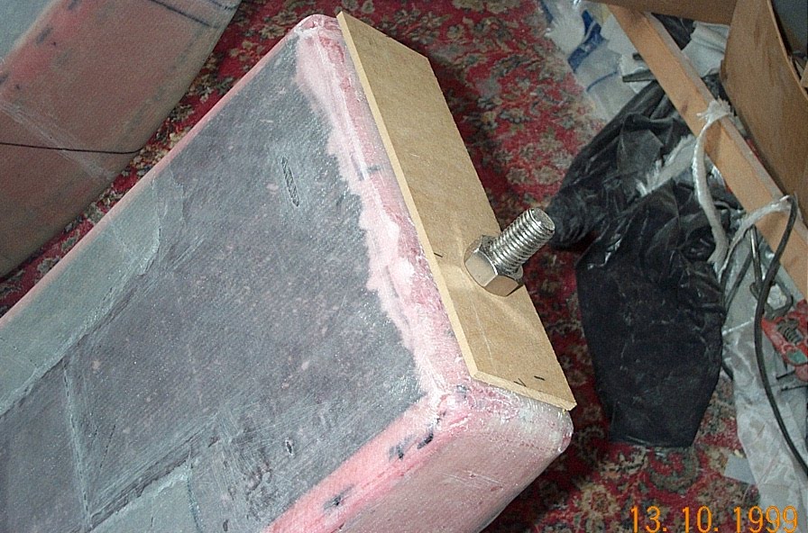
I was not very happy with the laminates around the bolt on the tip of the beam. When I did the "wraps", I slit the cloth and tucked it  around the bolt, but it did not co-operate, and left a lot of air and lumps and bumps. I decided to grind them out and fill with hd putty and patch as well. You then need to recreate a flat surface perpendicular to the bolt, for the nut to tighten up against.

I used the nut and some cut offs of MDF for that. Will be wrapped in plastic tape before use.

I thought I might as well make the float/ beam sleeves while I was at it. Made by wrapping fiberglass around the tip area and then pulling off.


Fairing mixture on the tips to just above the float deck level.

Fairing off the tips and re-drilling the pivot pin access holes in the beam sides. I found that shining a bright lamp down the slots in a darkened room lit up the pivot holes very well underneath the fiberglass. These holes had been sealed of with a foam plug and some hot glue. I was able to drill them very accurately using this method.

Tips faired off.. The geometry is such that the sleeve should not get locked on due to the shape. The tip is tapered up/down and sideways. In fact once you have managed to get the sleeve to move even a couple of mm, the whole thing should then slide off easily. (In theory!)


Resin proofing the tips. Parcel tape and wax. I find that although it is true to say that the resin does not stick to plastic tape, it still needs a bit of a jerk to come off. I may make a couple of handles somewhere on the sleeve to give me something to hold onto when I try to pull them off..


Getting the cloth ready. To be continued....


The bolt on the tip has been a constant nuisance, it is just begging to get damaged or covered in resin!


I made a raised ridge where the sleeve will be trimmed off , it should save me damaging the beam itself, and means there will be less sleeve to try and get off.


The sleeves laminated on.

I glued on the  bolt washer on the aft beams with HD putty, but this was not a good idea and just made them harder to get off.

After laminating, none of the sleeves would budge at all.! In the end I bonded on some wooden blocks and used a hammer to tap them off. But before that I did as much as I could to break the seal between the plastic tape and fiberglass. I used a 12V car tyre inflator to pump some air up the sleeve. This broke the resin/fiberglass seal in some places, but not over the tip or down the sides. It is also difficult to get a proper seal around the edge of the sleeve. I used some vacuum bagging rubber tape. Without breaking this resin fiberglass seal first, I very much doubt weather I could have got them off at all.

Wooden blocks bonded on the sides and pointing at the tip.


 Success. They are a very tight fit around the beams. When you pull them off, there is a suction/vacuum effect trying to hold them on. A small hole drilled in the tip helps to release them.

Aft beam sleeves finished. And no resin in the bolt threads.  FWD beam sleeves are still stuck fast, and the air compressor has broken down. (I may have burned it out by running it from a battery charger, I  am not sure.)

Anyway I am awaiting a replacement, as the sleeves will not budge at all without some more releasing under the fiberglass.

 Fwd beam sleeves finally finally off! Bastards! What a struggle - hours and hours of agro and frustration! Using compressed air did not work as it is virtually impossible to get a good seal around the sleeve. They would just not come off with tapping alone, (wood blocks got completely mashed with hammering) and in the end I  had no option but to try and cut them off, without damaging the beam. Not a happy situation to be in. I am doubly annoyed because my gut instinct when I laminated these on was that they would not come off. The shorter AFT sleeves yes, but not the longer FWD ones. The whole thing is a recipe for disaster. You cannot physically exert enough force to overcome the friction/tightness.

In the end I managed to push an old hacksaw blade partly up the middle of the sides, and then using a Feinmaster type cutter, I made 9 inch slits up the sleeve sides,  trying to cut on top of the hacksaw blade.  This released the tightness just enough to let me prise open the tops and bottoms with some very  thin wedges and push an old bandsaw blade up to the tip in places, thereby breaking the resin/plastic tape seal. Most of the time the blade just tears up the plastic tape and sticks, but I managed to break just enough of it so that it would tap off. The suction/vacuum effect is even stronger on these sleeves, and a hole drilled at the tip definately helps to prevent this.

I have to say nonsense like this really leaves a bitter taste and tarnishes your view of the whole project. You wonder how much punishment you want to take. I now have the pleasure of repairing the sleeves and some of the side layers on the beam itself. As a final insult, the plastic tape came off in 5000 pieces and left most of the stickness behind! Urgh!
On a lighter note thank heavens for Devcon 5-minute epoxy and the Bosch multi-tool!. The epoxy is expensive but very impressive. Within 10/15 minutes of bonding on the wooden blocks I was able to hit them with a small sledge hammer and they did not come off at all. I have had to cut/chisel the blocks off.

The multi-tool is definately my  2nd most usefull piece of kit (after the Black and Decker Power file). You can plunge cut into materials, and it cuts even fresh or thick laminate very well without damage. It is also cheaper then the Feinmaster.

Wednesday, 3 March 2010

More Beam work


After fitting the lids, the entire beam needs to be "wrapped" in 2 layers of fiberglass. This has proved to be the hardest task so far, it is partly a physical problem (beam is heavy and awkward to move), and partly a problem of how to "wrap" a curved object in flat cloth, without distortion. As you need access to the recess mould and folding system slots, it ideally needs to be upside down. You also need access all the way around, and yet need to support it.


Dry fitting the cloth in the reccess mould


and folding system slots (Actually I  found later that it is easier to cut the slots when the cloth is wet, otherwise it tends to start falling apart.)


I originally intended to try and do it in one shot, but as the top photo shows, this would involve upside down laminating, and having to move the tressels as you go along. In fact you have to cut the cloth so that the overlaps are in positions where you can move the tressels without the beam overbalancing. The alternative is to have to turn over a wet sticky beam half way through laminating, something I wished to avoid. I tried putting  it on its side, but it was not very stable, and the cloth around the curved area seems to distort more.


In the end I opted to do it in two stages.  Bottom and side overlaps in one stage, and then when dry, turn over and do the top and side overlaps. That way there is no need to move tressels or turn the thing over.The only downside is that because I need to do this wrap 2 times on each beam ( once before the carbon UD and once afterwards ) I shall have to do this lamination 16 times in total!

Bottoms done (FWD beams)


and tops. Now ready for the Carbon UD top and bottom


 250lm of Carbon UD. Expensive and really quite heavy. I don't find it particularly easy to work with in practice. The fibres are very densely packed.  It is slow to wet out and very difficult to to remove trapped air unless you over saturate it with resin. You can chase bubbles around endlessly. Also if you inadvertently snag a strand on something sharp, you quickly end up with a "bad hair day".


 FWD Beam bottoms finished. These are probably the hardest to do. There are XX layers on each, plus all the slots to be cut out. It is difficult to get the cloth in the right position first go. If you try and pull it off for a second attempt, it will unhelpfully pull up the layer underneath and start distorting. With so many layers I have used the slow hardener, to avoid heat build up, but it will have to be postcured at a later date. I am glad that the  Aft beams are shorter overall and have fewer layers!

 Laminating Carbon UD on the tops


Finished and peel-plyed.


Final wrap of fibreglass over the entire beam. Nearly there . Just some extra layers over the sides to do, then finished for now. Beam fairing will be added later after checking the folding system alignment when beams are attached to the hull.

I have to say that the beams are dissapointingly heavy, (but very solid!) With one across the tressels as above, I can lift the tip end up a few inches with one hand, but the overall weight must be in the 50/60Kg area I would guess. This will make folding/unfolding harder work I think.

I know that a finished F-32 beam with fairing weighs in at about 28Kg, and that according to an email I had from Ian about ready made F-39 beams, that they are " much bigger and stronger" than the F-32 ones

I could not find the exact weight of cloth as specified for the beams and had to use one that was 50g/m2 heavier, (with resin about 100g/m2) . This particular cloth also has slightly course pattern/texture, and even though you have thouroughly wetted the fabric, you still need to add extra resin to fill the pattern/texture, otherwise it will not peel-ply well. I reckon for about 2.5Kg of fabric, I am using about 3Kg of resin/hardener, which is not really very good,- excess weight.

I did have a much nicer cloth from my supplier at one point, but was unable to get any more. It was much smoother, soaked up resin quickly, conformed well around corners and peel-plyed very easily, but fell to bits very easily.  I wish now that I had taken the trouble to track down some more of this type.

On the plus side, for the multiple layers of Carbon UD, on the tops and bottom, I managed to use a bit less than 50/50 resin/glass. Generally I find that where you are laminating multiple  layers (about 3 or more) you seem to be able to use less that the standard 50/50 ratio.

Most of the overlaps I have made, (and there are quite few) are also a bit wider than neccessary, but the 45/45 cloth I am using tends to disintegrate along the edge when you cut it,  so to be on the safe side, you end up making the overlaps bigger. But again more extra weight.

I have also foam filled the beams which has probably added about 6/7 Kg I reckon. The Carbon anchor assembly probably weighed about 6Kg, and Upper folding slot recess about the same.

As I am going to postcure the beams anyway,  I wish I had made greater use of the slow hardener, -the mixture is a lot less viscous than the standard hardener mix, there is a longer working time and I think you can use less resin overall. Vacuum bagging would have helped, but would be a very awkward and long winded task. (At a brief look at the plans,  there must be over 100 different pieces of fiberglass in a beam altogether, not all full size, but a lot to deal with all the same) . Hopefully if I vacuum bag the hull and floats this will do something to even out the overall weight of the boat.

A few more beam construction photos...


Smoothing off after replacing the "removable"  strip ( actually they all came out in about 500 small bits and I had to cut 8 new pieces of foam!)

I have gone to a lot of trouble to try and keep everything smooth and flush at each stage , otherwise you tend to get small seams and patches of  air under laminates, and it is also difficult to consolidate the layers nicely. As you add more and more  layers, you  have more overlaps and patches and a few lumps and bumps etc,  and the smoothness/flatness gets lost .It makes getting the last few small air patches/ bubbes out very difficult. Rollers and squeeges tend to miss the dips and hollows.


Pivot pin holes sealed off ready for the all over "wraps" - aft beams


Wraped and ready for the Carbon UD - aft beams. Because I have done the "wrap" in two stages you tend to end up with a messy edge on the underside of the beam each time, drips and runs etc which need to be cleaned up before you can continue.


Carbon UD layers cut to side and laid out in order. Each piece is a different length and starts from a different position. A total of  108 layers required for all 4 beams. Fortunately I only made 1 mistake which was easily rectified.
Preparing the aft beams for the extra side layers. Then all beams finished except for a few small jobs like finding the pivot pin holes again!. The Aft beams are definately lighter than the forward beams, less layers of glass and Carbon overall. It is a long haul from start to finish with the beams and it gets rather monotonous having to do the the same job 4 or 8 ( or 16) times.  I am glad they are now finished.

Friday, 29 January 2010

Mast base

This (part) of the rotating  mast base is one of those maddening little pieces that is difficult to get right, because of all the shallow angles. If you get one bit correct and nicely fitting you then find another bit has gone slightly AWOL! Very frustrating.


It did not take too long to make the individual bits, but fitting it all together and working out 'how' to hold the parts in place for  welding (without loosing the pin alignment for the sheaves) has been quite tricky. The sheaves are running on a 1/2 inch stainless steel rod. I will drill sideways  holes either end of the rod and fit  clevis pins to keep everything in place, and allow for replacement of the sheaves if neccessary in the future


Sheaves fitted and now ready for welding.

Wednesday, 20 January 2010

Beams -Foam fill and top fitting

I have opted to foam fill the beams with a 2 part expanding polyurethane faom. It will add a bit of weight to each beam unfortnately, but hopefully not too much. I think I have used about 6/7 kilos per beam


It is a bit of a messy and laborious business. If you keep the 2 components at the optimum temerature for maximum expansion (least weight), then you do not get very long ( 45 secs) to mix well. i.e you have to mix lots and lots of small batches. The foam produces exothermic heat on expanding so it expands well, but then has an annoying habit of shrinking back slightly, leaving gaps around where it is touching the inside of the beam sides and bottom. Fortunately the next liquid pour and gravity  helps to fill these in.


If you spend too long mxing,  this happens! To get the foam into all the nooks and cranies, it reallly needs to be poured in whilst it is still completely liquid.


Here, I am cleaning up. I have tried to keep the foam off the areas that will later be usd as glueing surfaces for the lid.


Ready for the lid. This has been prelaminated already on the inside face.


Lid fitted.