Sunday, 20 April 2014

Hull Join Up

Bow pole/ forestay fitting, now with added threaded rod and wing nuts to hold out the bow pole. Threaded rod is embedded in HD putty mix, and moulded in half tubes, before laminating to the carbon fibre tube


Trial fitting the daggerboard case. Centered midway between the two halves, and at a fairly steep angle fore and aft.


Bow area, with the bow bulkhead and the bow pole bulkhead  (this with a hole cut out for the bow tube, and fitted at an angle). The plans suggest fitting this after the hull is joined up, but I thought it would be easier to get this fitted vertically  and at the correct angle now. It does restrict access a little to the inside of the bow, which needs to be taped, during join up.


On the whole the match between the two halves is very good. The  beam bulkneads match up well (which is a relief) , and that the pivot hole spacing is the same at the fwd and aft positions.


Wooden rod between the upper folding pivot points is to check distance between pivots is correct.


On the whole the two halves match very well ( both in shape and in a tight fit seam) but a few wooden block hot glued to the mould helps to keep the edges lined up nicely for glueing and taping.


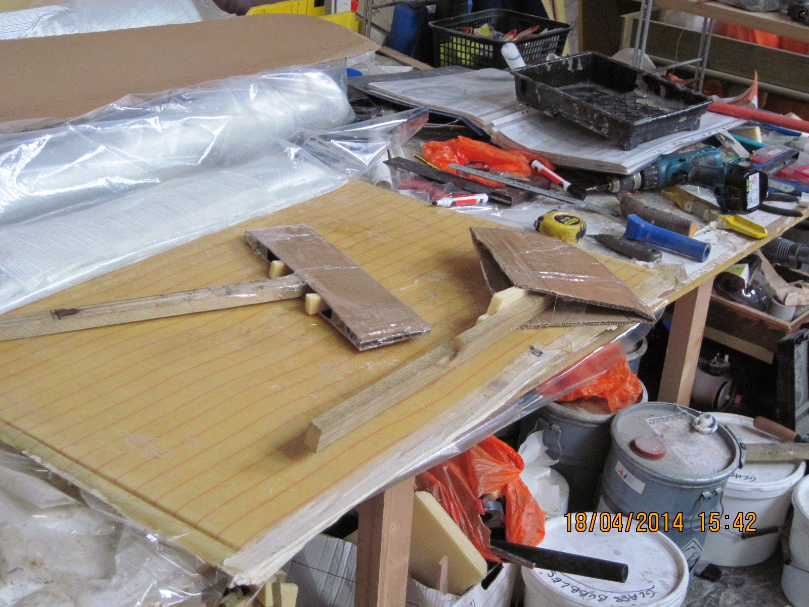
Highly advanced specialist tools made for positioning tape in those "hard to reach" to reach areas inside the bottom of the bow! Actually worked suprisingly well for once. I have had to cut an access hole in the bow bulkhead in order to get to this area of the bow.


Struggling..


Finally joined and taped. Bow pole still to be fitted and some extra layers to go on the fwd and aft beam bulkheads, and the daggerboard case to be taped in the upper half before completion.


Sunday, 29 September 2013

Beam Bulk/H and Carbon Anchor fitting

After the interior lamination is complete, the next task is the positioning and fitting of the carbon anchor assembly for the folding system, and then beam bulheads on top off them.

Aft beam bulkhead with side panels fitted.

Fwd Beam bulkhead, and post curing the anchor assembly after the additional laminates.

Heavy laminations over the anchor assembly. Very tricky to get the cloth to go down inbetween the slots without leaving air seams, and also to maintain the correct fiber orientation. I ended up splitting each layer into 3 pieces with additional patches over cuts and pleats.

Pre fitting foam for the foam/filler fill between the anchors. Then a few more laminates over this and then thankfully finished. A lot of work involved in fitting these 2 bulkheads, same job has to be done 4 times (either side of eachbulk/h, and made worse by hours of  knee cracking squatting on a sloping hull side.)

But beginning to look much more like a boat at last


Sunday, 7 July 2013

Planking cont...

Hull planking for this side now finished. I opted for 8" wide strips ( 6 per 4 x 8 ft sheet of foam) but it does mean a lot of seams to be filled/sanded flush.


I am hoping it will pay off in less filling and fairing being required later on.


I decided to use the dry lay up method this time. Partly because I am single handed on this project, and partly because some of the stitched fabrics are very awkward to deal with. Almost as soon as it is cut from the main  roll it seems intent on distorting and generally destroying itself! And the more you handle it the worse it gets. Trying to position it accurately onto a wet surface makes things even more tricky

Cunning device for positioning cloth with minimal hand contact. Partly successful. ( If you just let the roll drop the cloth bridges the hollows and then need  repositioning, causing more distortion) . The hull shape causes the fibre orientation to change a bit as the cloth goes down toward the gunwhale. I decided the keel area was probably the most important area to have correct.

Ready for resin.( I shall flip the overlaps back as I spread to help to get the resin right the way through the double layers to the foam)

Saturday, 15 June 2013

After a long cold winter and having to move location (fortunately within the same building) I have finally made a start on the second hull half.  On the whole the first hull half shape is pretty good, although there are a few uneven patches, where the foam strips did not lie tightly against the batons in the original mold, particularly on the tight corners down by the keel. I have opted to leave the outside of the first half unglassed for now and will do it after joining.

Mold re-assembled ready for planking, (and an indication of the final hull size and shape beam wise).


Fitting the Core-Cell strips. Core-Cell A500 seems to have been discontinued and is now repalced by M80. It seems to be a tougher foam and does not thermoform as easily.


Tight corners down toward the keel. Needs quite a lot of heating and some serious muscle to bend. Difficult not to scorch the foam.
View from the rear.

Sunday, 30 September 2012

Hull planking finished

Finally completed the planking and inside laminating of the first hull. Next fit carbon anchor assembly followed by the beam bulkhaeds.

Apologise for poor pictures. My new 12Mg pixel camera produces far worse photos than my ancient 2.6Mg pixel job. No substitute for descent optics.


Beam Bulkhards trial fit. (Camera crooked!) Basic position dictated by the tube through the sprocket sticking up from the frame below (cannot be seen, inside slot), and getting the top edge of the bulkhead horizontal with the hull sides, and in line with the frame.


Trying to get the upper folding slot pin parallel to the hull anchot pins. There is sufficient play in the set up to make mistakes. Bulkheads are heavy and unstable. Keep tipping forward becuase of heavy laminations around pivot pin. Tubes are for sighting through and the wooden struts (one each side of the bulkhead) is to keep bulkhead pivot hole parallel to carbon anchor pin.


Relationship between carbon hull anchors and beam bulkhead. Sighting through tubes looks OK, but it is all quite a tight and stiff fit. Tubes seem very prone to jamming in holes, very frustrating when you have to keep twisting in and out.

Ready for taping in place.


Sunday, 9 October 2011

Starting on the Main hull

I finally found a suitable space to rent to construct the hull and floats.  Continuing my back to front build, I have decided to get started on the main hull and leave the floats till later.


Form frames and battens. I made the chipboard form frames some time ago and found that they have all done a little bit of warping/twisting/splaying, and being generally unhelpfull. They are also in 2 parts as the 4'x8' sheets on their own are not tall enough. I have added extra height on some bottoms, and some have extensions on the tops. I have had to spend a lot of time geting them back to upright, flat, sqaure etc.


   If I ever did this again, I think I would avoid using chipboard. It is heavy, brittle and prone to distorting. Any money I saved by using this rather than MDF, has probably been spent on expensive jigsaw blades to cut the stuff!  Beginning of the planking


I have copied Henny's (fram.nl) method of using battens to temporarily hold the foam rather than clamps but with the addition of a small block on the batten to keep the edges butted up tight together.


 I have opted for 9' wide strips, -it does mean a lot of strips to fit, and many seams to be filled, but I found it quicker to thermoform and fit this size rather than struggle with wider pieces. If you give the foam too much heating it tends to expand and distort. I give it just enough to take out the stress and relax enough for the screws to hold it well from behind.

Saturday, 20 November 2010

Beam Baking

I am using a similar arrangement as before, but with an additional 60W bulb. 6 in total. Could really have done with 7 to speed up the process and produce some extra heat.


Bearing in mind that there is 60/70Kg of resin and glass in the beams, it is going to be a slow process to heat them up to 50C. There are 25 plus layers of carbon and glass in places, and the heat is going to take a long time to reach everywhere.


I wanted the hot air to be able to circulate all around the beam, hence the side struts to lift up the cardboard.


Cardboard creation. Unfortunately the heat loss from this was too much, and I had to add a lot of blankets and some old rugs to keep the heat in. Coud have done with another bulb, but would exceed my dimmer switch wattage rating..


Initially the heat distribution was rather poor. The hot air was trapped underneath the beam by the sides of the ladder,  and was not getting up to the top surface well (15C difference between top and bottom). I had to add 2 small hot air/cool blower fans (8.99 GBP - Amazon!)  in at each end to circulate the air better.

Finally getting up to temp after about 36 hours! The light bulb method is v slow for a big heavy part like this, but on the other hand you do not have to worry about it all going ballistic and frying the thing while you are away.  I think the maximum heat you can get from this arrangement with no heat losses would probably be about 60C, which would not do any damage.

Sunday, 14 November 2010

Postcuring daggerboard and rudder

I thought it would be a good to idea to postcure the daggerboard and rudder parts for extra strength, as they are not going to be exposed to much  heat  when in position. It is not strictly neccessary, as I have not been using slow hardener on these parts. The beams on the otherhand I will have to postcure as I used slow hardener on the multiple layers of carbon UD.
  
 I am reasonably happy with the foil shape. although it has taken more filler/fairing mix than I had hoped for. I used a template CNC cut from the daggerboard DXF file  for the final shaping. Strictly speaking I think I should have postcured before filling and fairing. Hope all the filler does not shrink and crack off!


The heat source. 5 x 60W light bulbs plus dimmer switch. I  have found this to be very controllable.


Heat source under the board. The bottom edge of the board did get a bit hotter than the top, but on the whole the heat rising up from below was quite well distributed., about 5C difference between top and bottom. 


Rather crude cardboard oven. But it did the trick OK ( with a bit of additional room heating to cover the heat loss from the cardboard) . It is suprising how long a large piece like this takes to heat up. (and cool down!) You begin to think that you are not giving it enough heat, but in reality most of it it is being absorbed by the board for the first  few hours or so. After that you can begin to actual get the temp up a bit. As the board has a wooden core, I did not want to get it too hot. In the end it had about 24hours at about 45C. (Cure for the resin I am using is 50C for 16 hours.) Hopefully this will be about equivalent.


Oven No:2 for the rudder/sleeve/gudgeons/composite chainplates/bowpole/forestay backet fitting. A smaller volume to heat up, should be a bit quicker hopefully.

Friday, 22 October 2010

Rudder Case

The rudder case design is such that the rudder blade itself can be raised up and down as neccessary for getting in and out of shallow water. This gives better steering control than the kick back style of rudder where very little of the blade is in actual contact with the water.

Sleeves is made by laminating around the rudder blade itself. Flanges made from some foam cut offs, and will be pulled off after laminating


I think the idea that the sleeve will slide off sideways is a little optomistic. Fortunately because the trailing edge end is open, you can prise the sleeve sides apart slightly. Then I pulled some thin strong string down to the leading edge each side, (breaking the resin/tape seal) -then with a tap from a rubber hammer, it just jolts forward slightly and then could be worked off.

Case off, make sure you get it the right way up for trimming! The top and bottom angles are not the same.


Attaching the tube to the sleeve and getting it parallel and perpendicular is tricky to get right, -get it wrong and have wonky rudder! I thought this set up plus gravity should help, as there is very little in the way of referrence points to tell if it is correct or not.
 
.
Final laminations added - now need to cut slots for the gudgeons


Slots for gudgeons. Angle grinder and power file. Very messy- black dust everywhere. (Case shown upside down)


Marine carpet for the case lining? Well I hope so. I asked Ian Farrier what  "marine carpet" was, and he directed me here, (but also said that it is no longer available!) :

http://www.office-furniture.com.au/Fabric-Options/Fabric-Options/Front-Runner-Fabric-Range.html

However it still seems to be available in the UK -as shown above . It appears to be the same material (named - Front Runner Fabric) - it matches the description well .But it does seem thinner than I was expecting. In the uncompressed state it is about 3mm thick, but when squashed goes down to about 1.5mm. I may need to use a double layer I think. (Actually IF say do not use 2 layers, rudder would move in sleeve and steering would be spongy/rubbery)
  
 Attaching the steering arm to the case.


Mold for making a removable sleeve. The flange plate is my idea to help pull of  the sleeve after laminating.


Sleeve laminated on. These small pieces of cloth are a pain to cut and work with. They keep on lifting off around corners and are prone to distorting badly.


Trial fitting the quadrant, -getting it  perpendicular to the pivot pin is important. I am still not entirely happy with the carbon quadrant, and have decided to line the slots with 3mm Aluminium to try and prevent the steering wire from eroding the carbon over time.